The mechanical design started with the shooting mechanism. Because reliability was the most important feature of our shooting mechanism, the design went through several iterations.
Initial Shooter Calculations
With the robot stationary at the server, what launch angles enable the coin to successfully reach both the center and side deposit bins?
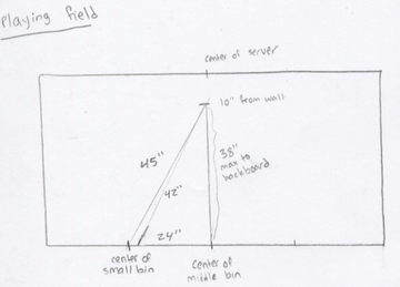
The picture to the right shows a top view of the playing field with the distances to the bins. We assumed the coin would be launched from a vertical height of 10" and a distance of 10" away from the server wall.
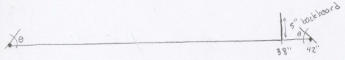
For a worst-case maximum angle, at least half of the 1.5” diameter poker chip must hit the backboard of the large deposit bin. The angle corresponding to 4.25” vertical and 4” horizontal displacement is 46°. The design will incorporate a launch angle of less than 46°, with the minimum angle determined through testing.
The picture to the right shows a top view of the playing field with the distances to the bins. We assumed the coin would be launched from a vertical height of 10" and a distance of 10" away from the server wall.
For a worst-case maximum angle, at least half of the 1.5” diameter poker chip must hit the backboard of the large deposit bin. The angle corresponding to 4.25” vertical and 4” horizontal displacement is 46°. The design will incorporate a launch angle of less than 46°, with the minimum angle determined through testing.
Design
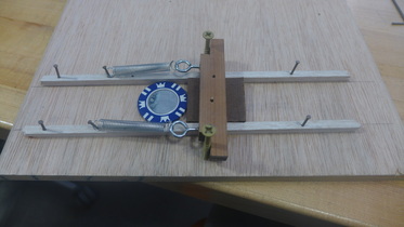
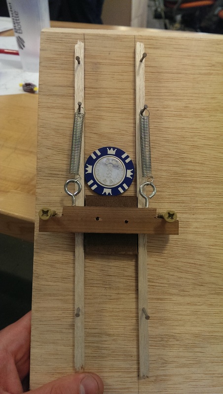
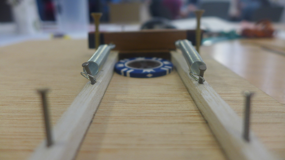
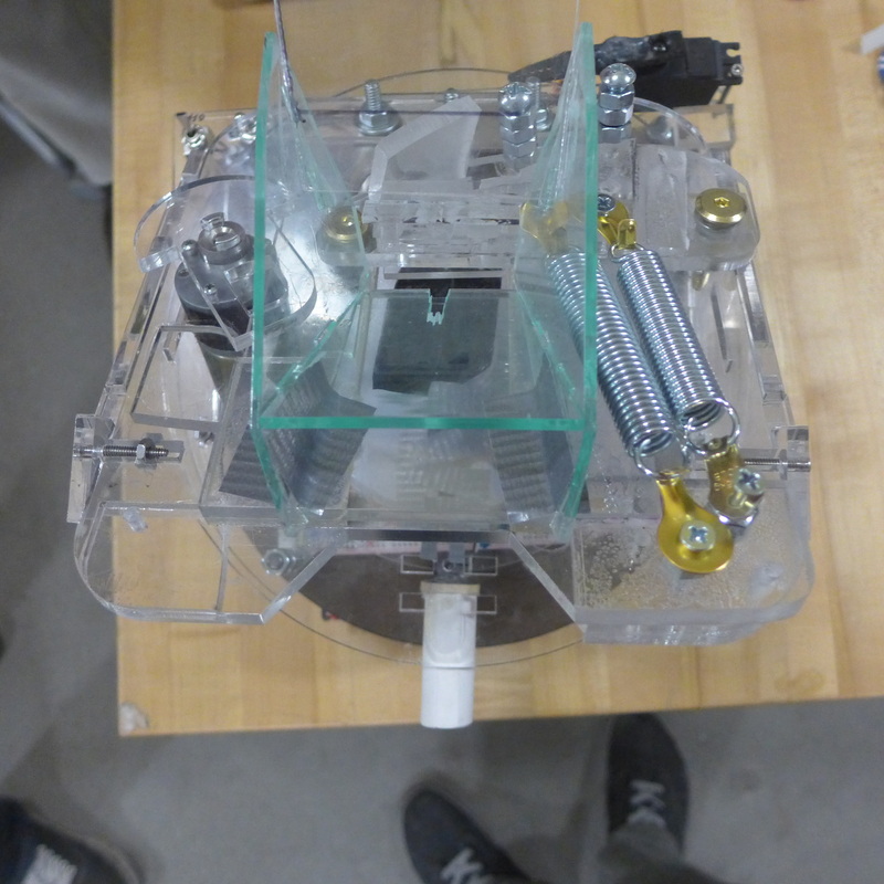
The first two iterations were made out of wood and tension springs. These served as a proof of concept for the shooting mechanism. The spring design was chosen to prevent any variation in the shooting distance due to power supply. We considered using a spinning wheel bumper that grabs poker chips and throws them, however, this is dependent on the motor speed and thus the voltage supply, so an encoder is needed to compensate.
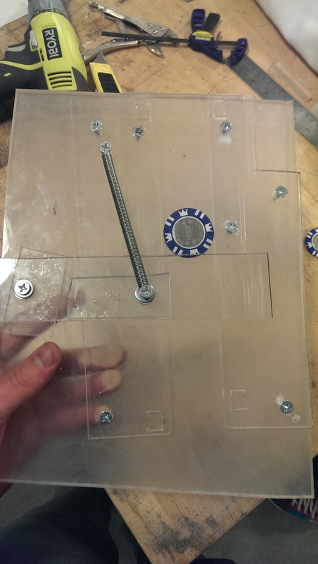
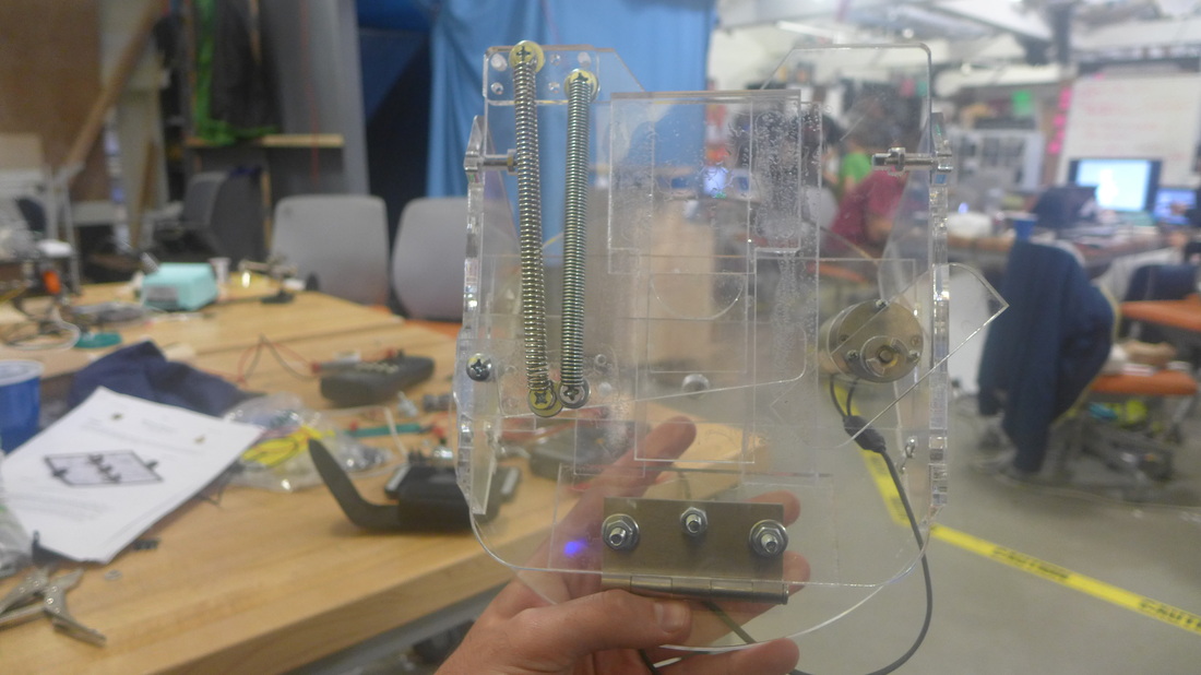
The third iteration of the design was made out of scraps of acrylic. This design tested the durability of the acrylic and whether or not it was feasible to reduce the design down to the size constraints in the specifications. Reliability was also tested, and our first shooting test at the desired range was done.
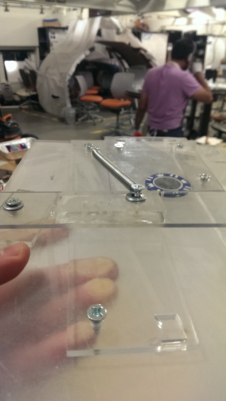
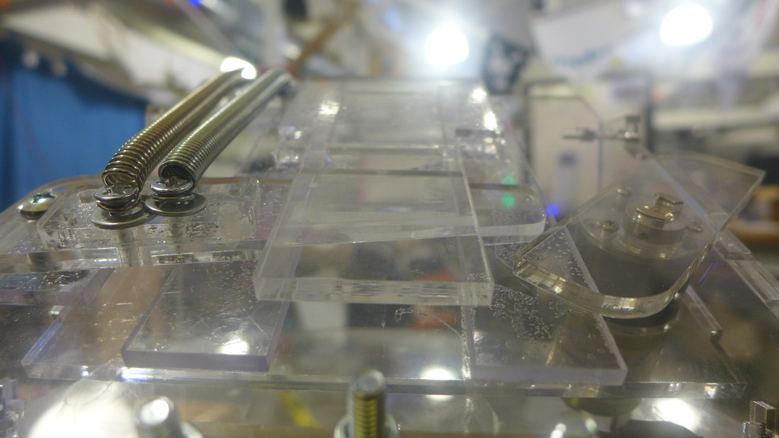
The fourth iteration was designed in SolidWorks and cut out of a single acrylic sheet on the LaserCAMM. This design was allowed us to test and make modifications as needed. It also provided insight on how best to mount the shooter to the base and what features needed to change in order to accommodate a funnel.
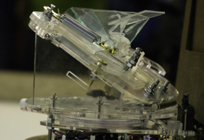
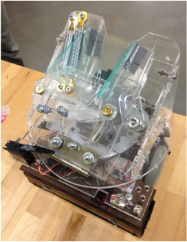
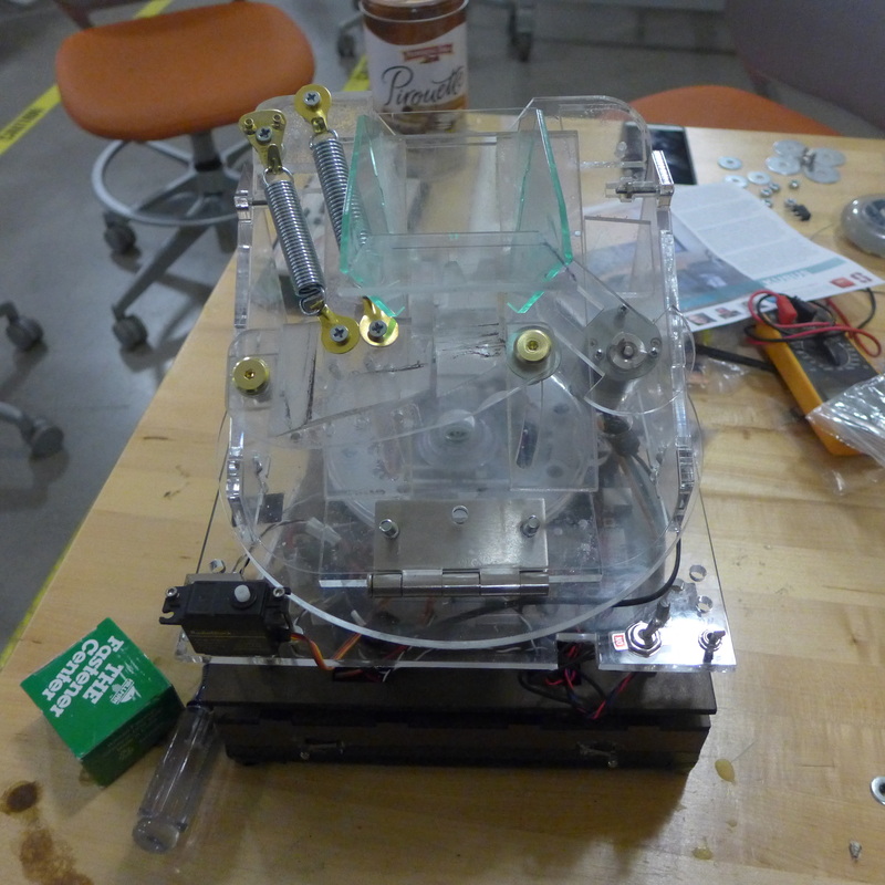
The fifth and final iteration was used in the competition. The funnel was permanently attached and the base screwed into the drivetrain portion of the robot.