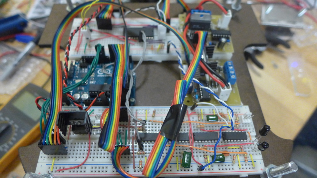
Components
Microcontroller
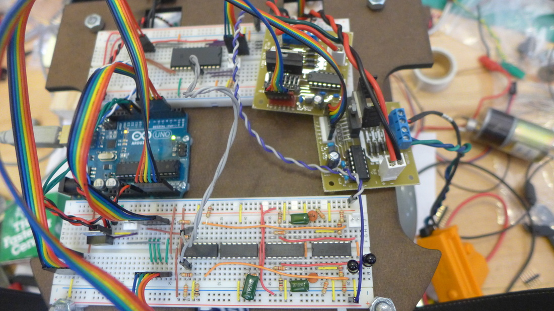
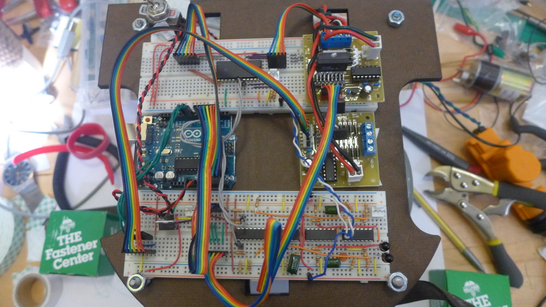
1 Arduino Uno
Other ICs
2 L298 Motor Driver boards
1 Multiplexer 74HC4067
3 Opamps LM324
1 Comparator LM339N
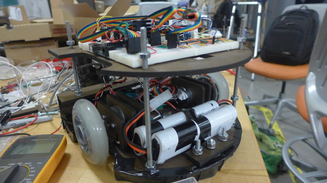
Power components
2 7.4 NiCd Batteries in series
2 LM7805 Voltage Regulator ICs for powering the circuits and the servo motors
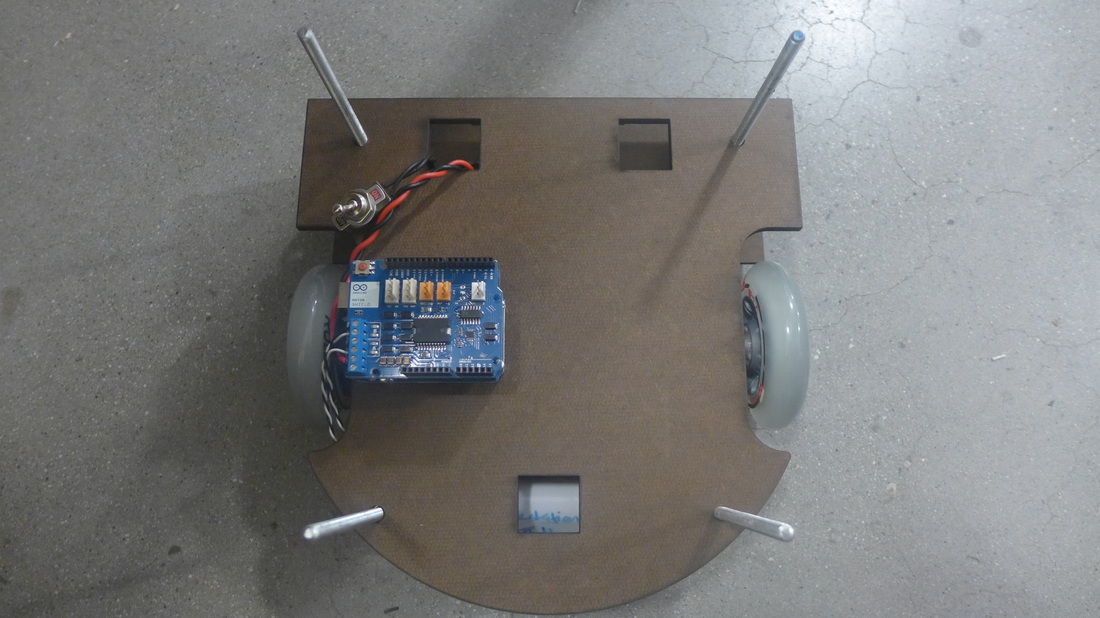
Actuators
2 60rpm DC motors (wheels)
1 60rpm DC motor (shooter)
1 servo motor (button press)
1 servo motor (shooter rotation)
Sensors
1 IR Phototransistor for beacon sensing
1 Photoresistor for coin detection
3 tape sensors (phototransistor reflective object sensor)
2 momentary switches for wall bump sensing
1 Enable flip switch
1 Arduino Uno
Other ICs
2 L298 Motor Driver boards
1 Multiplexer 74HC4067
3 Opamps LM324
1 Comparator LM339N
Power components
2 7.4 NiCd Batteries in series
2 LM7805 Voltage Regulator ICs for powering the circuits and the servo motors
Actuators
2 60rpm DC motors (wheels)
1 60rpm DC motor (shooter)
1 servo motor (button press)
1 servo motor (shooter rotation)
Sensors
1 IR Phototransistor for beacon sensing
1 Photoresistor for coin detection
3 tape sensors (phototransistor reflective object sensor)
2 momentary switches for wall bump sensing
1 Enable flip switch
Schematic
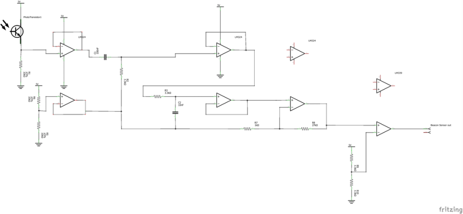
Beacon Sensing
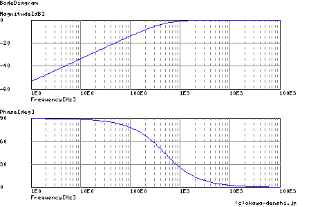
The signal from the phototransistor is passed through a buffer, then through a low pass and a high pass filter. It is then amplified and run through a comparator, and the output is fed to the Arduino Uno Interrupt 0 pin - pin 2. We use the timing between interrupts to detect the frequency of the beacon being sensed.
The signal from the phototransistor is passed through a buffer, then through a low pass and a high pass filter. It is then amplified and run through a comparator, and the output is fed to the Arduino Uno Interrupt 0 pin - pin 2. We use the timing between interrupts to detect the frequency of the beacon being sensed.
|
High pass filter (remove background light (0Hz), and interference from fluorescent lights(60Hz) etc)
R = 3.3k, C=0.1u Cutoff Freq = 482 Hz 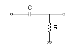
|
Low pass filter (remove high frequency noise, if any)
R = 3.3k, C = 10n Cutoff Freq = 4822Hz 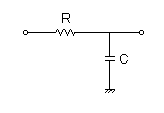
|
Tape Sensing
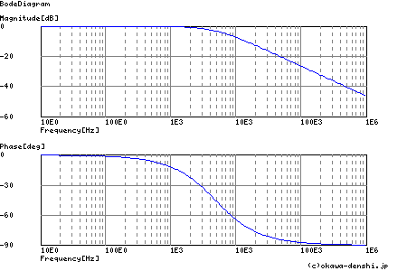
Three LED-Phototransistor pairs were used for tape detection - one right in the middle between the two wheels, and two kept a tape-width apart in the back.
The wiring for one of them is shown here.
Three LED-Phototransistor pairs were used for tape detection - one right in the middle between the two wheels, and two kept a tape-width apart in the back.
The wiring for one of them is shown here.
Pins
Arduino Uno Pins used:
A0 to A3 (OUTPUT, Digital) - Mux select pins
A4 (INPUT) - Mux common input
Beacon Sensor (INPUT) - Pin 2
Right Wheel direction (OUTPUT, Digital) - Pin 4
Right Wheel enable (OUTPUT, PWM) - Pin 3
Left Wheel direction (OUTPUT, Digital) - Pin 7
Left Wheel enable (OUTPUT, PWM) - Pin 5
Shooter rotation Servo (OUTPUT, DIGITAL) - Pin 6
Shooter DC motor (OUTPUT, DIGITAL) - Pin 9
Button Press Servo (OUTPUT, DIGITAL) - Pin 11
Multiplexer 74HC4067 Pins:
Front Line Sensor 6
Back Line Sensor Right 5
Back Line Sensor Left 4
Wall Switch Left 9
Wall Switch Right 10
Coin Sensor 13
Enable Switch 14